1. What Is Phenolic Pre-insulated Duct
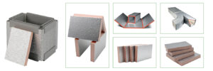
Phenolic pre-insulated duct combines the advantages of traditional materials and modern technology, enhancing the insulation performance of the panel while improving surface strength and fire resistance. It also features waterproofing, odorless and non-toxic properties, corrosion resistance, crack and deformation resistance, flame retardancy, high strength with lightweight characteristics, easy installation, and long service life.
Based on GFI Duct’s extensive experience in manufacturing pre-insulated ducts, this article introduces the conventional manufacturing processes and methods for phenolic pre-insulated ducts, including layout marking, cutting, forming, reinforcement, connection, and suspension.

2. Layout Marking Process
Before marking, it is essential to fully interpret the HVAC duct installation drawings, determine the installation locations of air conditioning equipment and duct components, confirm the appropriate lengths and quantities of straight ducts and fittings, specify connection methods between ducts and equipment, and calculate the material requirements, including panels and auxiliary materials.
2.1 Layout Marking for Rectangular Straight Ducts
2.1.1 Calculating the Layout Dimensions
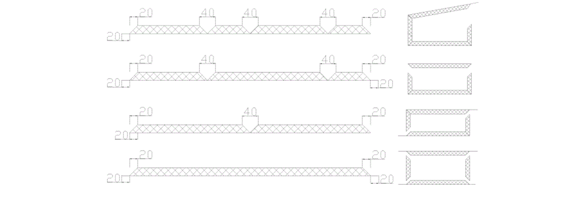
When manufacturing rectangular phenolic ducts from panels, the dimensions marked on the duct indicate the internal dimensions. Each panel edge should be cut at a 45-degree bevel. Four panels are assembled to form a rectangular duct. For a 20mm thick panel, each panel edge should be 40mm longer than the internal duct edge.
Rectangular phenolic ducts can be assembled using different methods, including single-panel assembly, U-shaped two-panel assembly, L-shaped two-panel assembly, and four-panel assembly. The marking dimensions vary depending on the selected assembly method. The layout dimensions should be calculated according to the duct manufacturing task sheet.
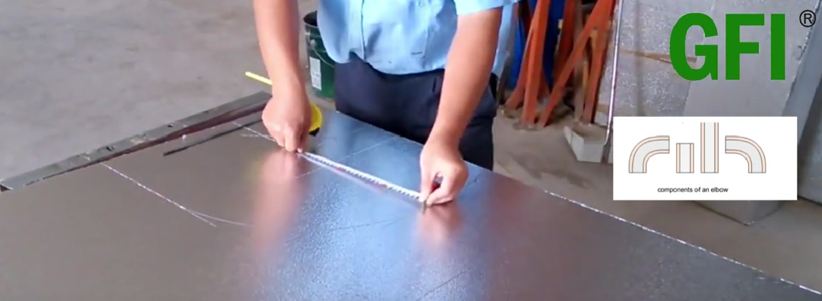
Using a steel ruler or measuring tape, measure the required dimensions on the panel. Use an aluminum straightedge and a marker to draw the cutting lines, V-groove lines, and 45-degree bevel lines on the panel.
2.1.2 Layout Marking for T-shaped
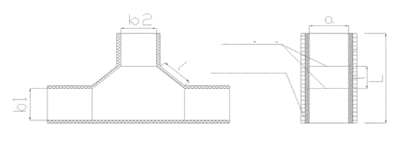
2.1.3 Layout Marking for Phenolic Duct Elbows and S-shaped Bends
Rectangular elbows generally consist of four panels. First, mark the side panel shape on the material according to the design requirements. Then measure the bending edge length of the side panel and mark the inner and outer arc panel shapes accordingly. Draw the cutting lines, 45-degree bevel lines, and bending area lines.
2.1.4 Layout Marking for Transition Ducts
A rectangular transition duct is usually composed of four panels. First, mark the side panels according to the design requirements, then measure the transition edge length and mark the upper panel accordingly. Draw the cutting lines, 45-degree bevel lines, and bending or V-groove lines.
2.1.5 Layout Marking for Branch
There are various types of branch ducts. For an R-shaped branch duct, first mark the upper and lower cover plates as shown in the diagram. Measure and mark the inner arc panel length, followed by the outer arc panel length. Draw the cutting lines and 45-degree bevel lines.
3. Phenolic Duct Panel Cutting Process
Before cutting, check whether the layout marking aligns with the duct manufacturing task sheet, verify the accuracy of the markings, and inspect the material for damage. Also, ensure that the cutting tools are securely installed and that the blade height is set correctly.
- The height of the straight knife blade should be sufficient to cut through the panel without damaging the work surface.
- The height of the single-blade and double-blade slotting knives should be enough to cut through the upper aluminum foil and core material without damaging the lower layer.
- The spacing between the two blades should be approximately 2mm.
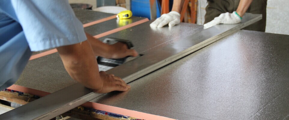
Select the appropriate left or right 45-degree single-blade slotting knife based on the edge-cutting requirements. Position the panel on the workbench, align and secure the aluminum straightedge at the correct position, and use the tool along the straightedge to cut the material.
- A straight knife is used to cut through the panel completely.
- A single-blade knife is used for edge trimming.
- A double-blade knife is used for slotting.
After cutting the panel into individual duct sections, number them to prevent mixing. For elbows, evenly spaced slots should be cut to facilitate manual bending.
4. Phenolic Duct Forming Process
Inspect the duct panels according to the task sheet to ensure compliance with design requirements.
- Clean the cutting edges of any dust, grease, or moisture.
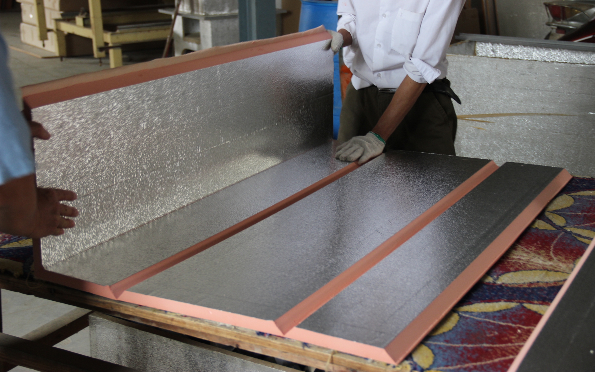
- Apply adhesive with a brush to the cut edges. Once the adhesive is tack-free, assemble the duct panels as per design requirements and press them flat using a scraper.
- For difficult-to-flatten areas, use a wooden mallet for gentle tapping.
- Check that the panel joints meet quality standards.
- Once the seams are secure, bend the edges to 90 degrees and fasten them with rivets at intervals no greater than 10cm.
- Load sealant into a sealant gun, clean the inner corner edges, and apply sealant evenly. Press the sealant firmly to ensure airtight sealing.
- Use a steel ruler and square to check the formed duct for dimensional accuracy.
5. Phenolic Duct Reinforcement Process
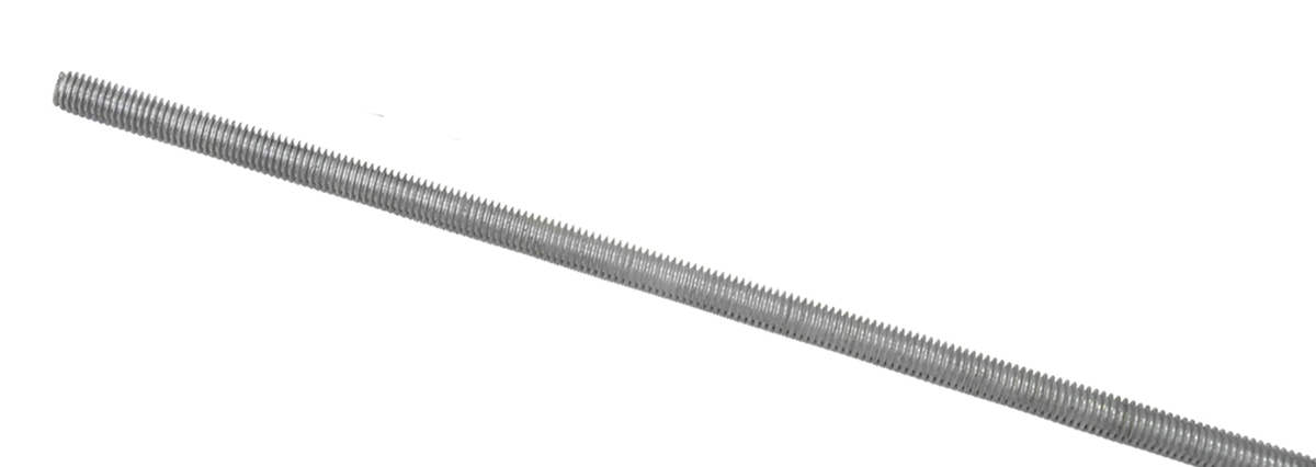
Full-threaded rods are commonly used for reinforcement, secured with double nuts at duct connection points and sealed with adhesive. In areas with stringent requirements, single-angle steel flanges or double-angle steel flanges should be used for additional reinforcement.
6. Phenolic Duct Connection Process
6.1 Connection with Insert Flanges
- Ensure that the duct ends are perpendicular. Correct any uneven or non-perpendicular sections.
- Select appropriate duct connectors and verify their quality.
- Cut the connector material to size using a profile cutting machine, ensuring that the length is 2-4mm shorter than the duct’s internal edge.
- Apply adhesive to the duct ends and the corner gasket.
- Insert the connector into the duct end with the short side facing inward. Press firmly or tap lightly with a wooden mallet.
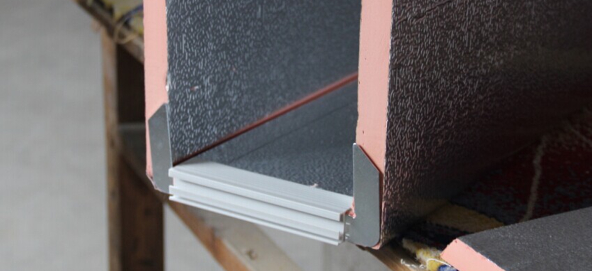
- Insert an I-shaped strip between the two duct sections for connection.
- Seal the joint with sealant and install the corner covers.


6.2 Connection with H, F, and U-type Duct Flanges
Select the appropriate flange shape for the connection. Cut both ends of the flange at a 45-degree angle. Apply adhesive to the duct corners and adhere the flange to the duct, sealing the inner seam with sealant.
6.3 Direct Panel Connection and Splicing
For ducts with an edge length of ≤500mm, panels can be directly connected. After cutting, clean the adhesive surfaces, apply adhesive, and insert the panels into an I-shaped reinforcement strip. Press tightly and seal the seams with sealant.
6.4 End Plate Connection
Cut both the duct end and end plate at a 45-degree bevel, leaving a 20mm protective edge on the end plate. Apply adhesive to the cut edges, bond them directly, and secure the joint with aluminum foil tape.
- Key considerations during connection:
- The bonded duct connectors must be secure and straight.
- The four corners of the duct connector should be on the same plane and perpendicular to the duct’s extension.
- Inner sealing must be smooth and airtight.
- The connection direction must be correct.
- Dimensional tolerances for flanges must comply with the standards.
For ducts exceeding 2000mm (low-pressure) or 1500mm (medium-pressure), flanges should be made of aluminum alloy or other metal materials.
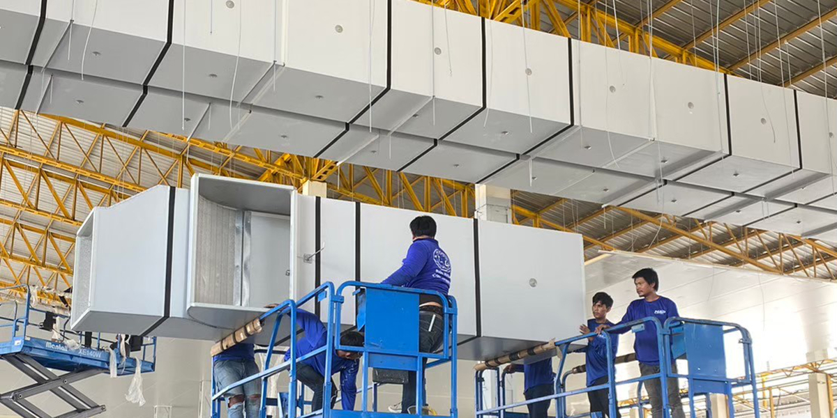
7. Phenolic Duct Suspension Process
- Inspect duct quality.
- Drill expansion sleeve holes in the supporting material.
- Fabricate suspension rods using full-threaded screws.
- Install the suspension rods.
- Cut, drill, and anti-corrosion treat the cross supports.
- Suspend the duct and install vibration damping pads.
- Install duct connections and ventilation components.
- Apply insulation to metal flanges and ventilation components.